Since its first installation in 2005, the NanoESCA concept benefited from many customer feedback, continuous improvements and a deep understanding of its inherent possibilities. The many fascinating scientific results and methods published with this instrument speak for itself. During the last two years we reviewed and revised some elements, which lifts the analyzer to a new level. With its abilities to perform both, Momentum and Real Space Imaging Spectroscopy, in ultra high resolutions, it seeks to become the photoemission analyzer for the next generation of scientists: NanoESCA · MARIS.
New Highlights
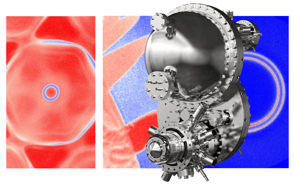
The pictures in the cover image feature popular measurement capabilities of the NanoESCA analyzer, like measuring the full Brillouin zone of a Fermi level in one snapshot, the Real Space Image of magnetic domains measured with the Imaging Spin Filter, or the Rashba split surface state of Au, acquired with a momentum resolution < 0.005 Å-1 .
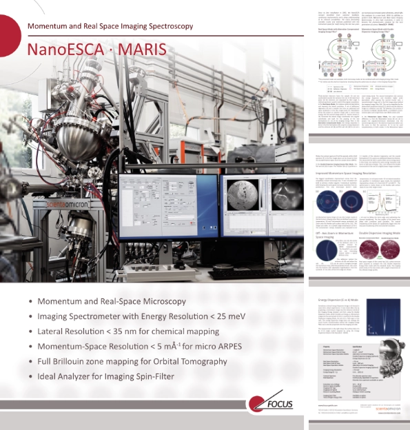
New Brochure
The information on this webpage is also available as a four-page brochure for downloading, sharing and printing:
A variety of operation modes
Real Space Mode with Aberration Corrected Imaging Energy Filter*
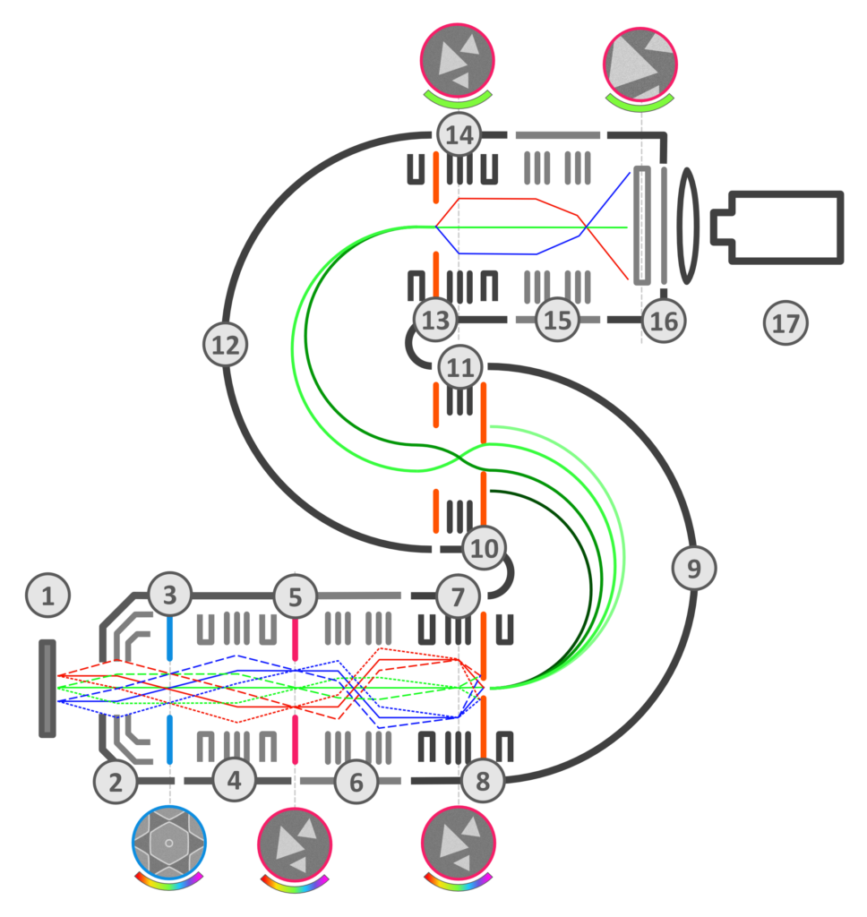
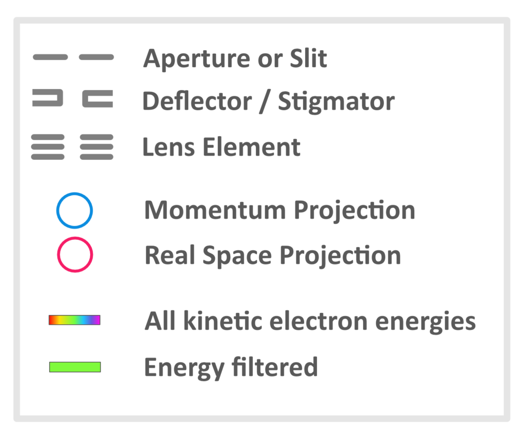
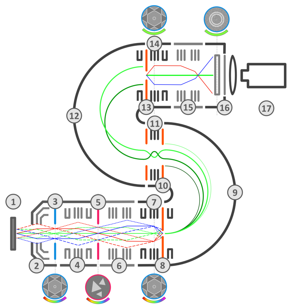
Photo-excited electrons leave the sample (1) and are accelerated towards the extractor lens (2). In the back focal plane (3) the electrons are separated by their angle. A contrast aperture is used to restrict the angular acceptance. In the Real Space Mode, this reduces spherical aberrations and improves the lateral resolution. A set of deflectors/ stigmators (4) and a transfer lens form an optimized real space projection in the first image plane (5). Retardation lenses (6) project an electron image with a correct pass energy into the second image plane (7). Fourier lenses (7, 14) transcode the lateral image coordinates into angular coordinates and back for the passing of the two hemispheres (9, 12) of the Imaging Energy Filter.
In the Aberration Corrected Mode, the energy separation is done in the first hemisphere (9) using the energy dispersion and the entrance slit (8) and first exit slit (10) to cut out a small energy band. The second hemisphere (12) corrects the energy dis Photo-excited electrons leave the sample (1) and are accelerated towards the extractor lens (2). In the back focal plane (3) the electrons are separated by their angle. A contrast aperture is used to restrict the angular acceptance.
Momentum Space Mode with Double
Dispersive Imaging Energy Filter*
In the Real Space Mode, this reduces spherical aberrations and improves the lateral resolution. A set of deflectors/ stigmators (4) and a transfer lens form an optimized real space projection in the first image plane (5). Retardation lenses (6) project an electron image with a correct pass energy into the second image plane (7). Fourier lenses (7, 14) transcode the lateral image coordinates into angular coordinates and back for the passing of the two hemispheres (9, 12) of the Imaging Energy Filter. In the Aberration Corrected Mode, the energy separation is done in the first hemisphere (9) using the energy dispersion and the entrance slit (8) and first exit slit (10) to cut out a small energy band. The second hemisphere (12) corrects the energy dispersion and therefore higher order aberrations.
After passing the second Fourier lens, a monochromatic image sits in the first image plane behind the Imaging Energy Filter (14). This can be magnified by the downstream projection lenses (15), which map the electron image on a detector unit (16). The detector unit consists of an electron multiplier (Double MCP), a scintillation screen, camera optics and a high frame rate CMOS camera (17). In the Momentum Space Mode, the only essential difference is, that the Retardation lenses (6) are set to project the angular/momentum distribution into the second image plane (7). The electron trajectories before are the same, so that the apertures (3, 5) can be used complementary in both modes. In the Momentum Space Mode, the contrast aperture (3) will be opened, while a field aperture (5) in the first image plane can be closed to limit the accepted lateral region from the sample (micro ARPES). In the Double Dispersive Imaging Energy Filter Mode, the first exit slit (10) is open. The Transfer Lens (11) performs a 1:1 transfer of the electron trajectories and the second hemisphere (12) is used as an additional dispersive element. The second exit slit (13) is used to filter out an energy band. In this mode, one reaches the same energy resolution with twice as high pass energies. Thus one achieves the double transmission at the cost of a slightly lower image resolution.
*The presented modes are examples. Each microscopy mode can be combined with each Imaging Energy Filter mode.
** For clarity only the electron trajectories traveling along the optical axis are shown in the Imaging Energy Filter.
Improved Momentum Space Imaging Resolution
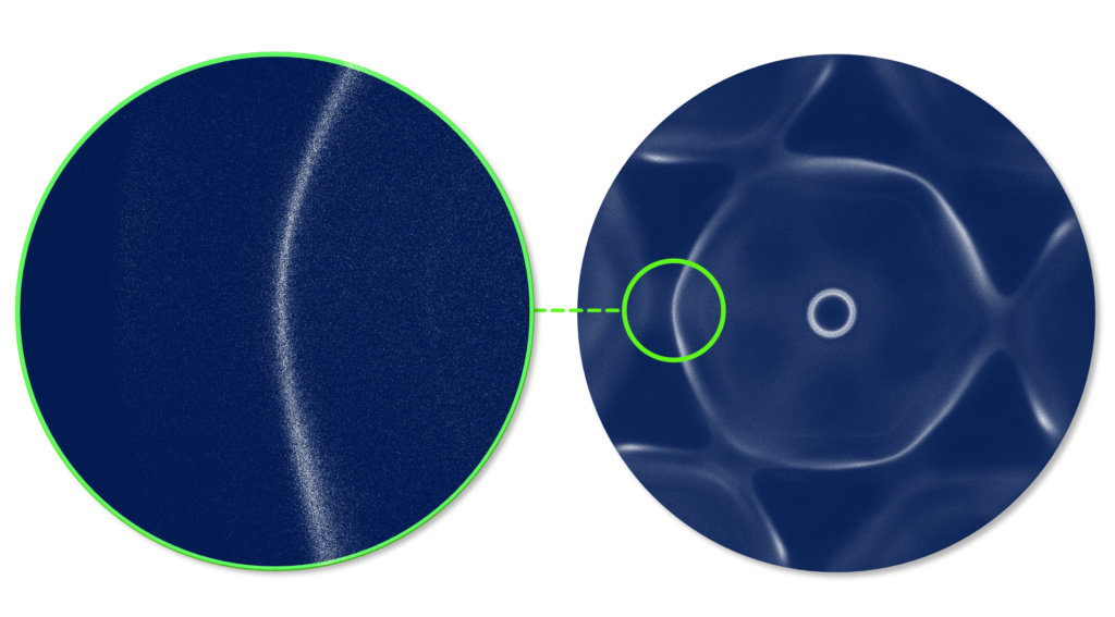
The biggest specification improvement comes from the completely revised microscope lens. It was simulated and build to achieve a better angular / momentum resolution while keeping the same good real space resolution from its predecessor. This new microscope doesn’t make compromises. In real space mode < 35 nm lateral resolution are specified. In momentum space mode, the resolution improved by a factor of 3, from 0.015 Å-1 to 0.005 Å-1. The performance is nicely shown on the Rashba split surface state of a Au (111) single crystal.
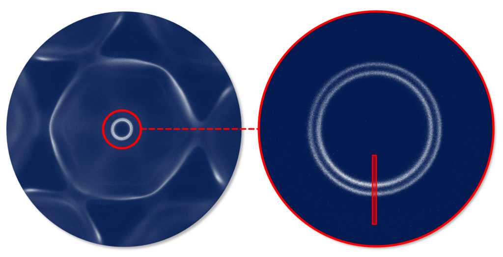
Left: Momentum Space Image of a Au (111) single crystal at the Fermi level, showing more than one Brillouin zone (room temperature, 50 meV instrumental energy resolution).
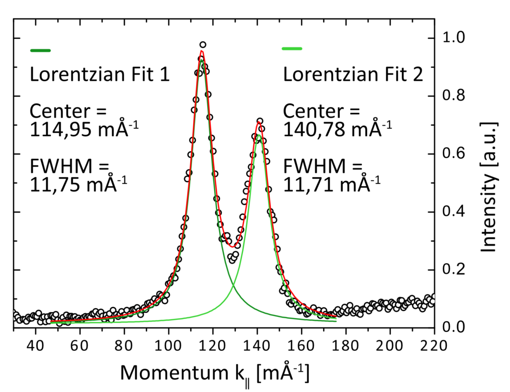
Right: Zoom onto the Rashba split surface state of Au (111). This image was taken at a sample stage temperature of 45 K. The instrumental energy resolution was evaluated to be < 24 meV by fiting the Fermi edge and subtracting the thermal broadening.
The line profiles of the bands were fitted with Lorentzian peak functions. The natural broadening of the bands are significantly bigger than the Gaussian broadening of the instrumental resolution.
Off – Axis Zoom in Momentum Space Imaging
the Brillouin zone is of scientific interest for ARPES measurements. The NanoESCA can zoom into any interesting feature within a typical Brillouin zone.
The deflectors behind the entrance slit (8) and before the exit slit (13) can be used to navigate through the momentum map, while the projection lenses (15) zoom into the features with adjustable magnifications. Here the sp-bands of Au (111) at the Fermi edge are shown.
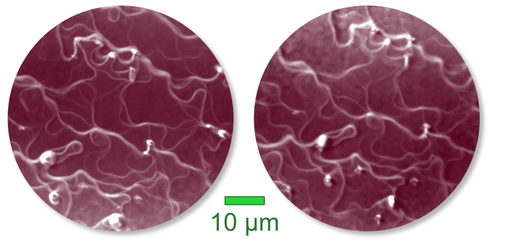
Double Dispersive Mode
Real space images of (the same) Ag (111) surface terraces were acquired to compare the new Double Dispersive Energy Filter mode with the standard mode. The imaging works nicely in the new mode, with a slight compromise on the ultimate image quality.
Left: The image was aquired in the standard Aberration corrected mode. Right: The same sample was aquired with the same settings, but in the Double Dispersive Mode of the NanoESCA.
Energy Dispersion (E vs k) Mode
Sometimes a direct Energy Dispersion Image is of interest in some time critical experiments. A new mode offers this by projecting a momentum image into the entrance slit (8) of the Imaging Energy Analyzer and then using the Double Dispersive mode, which transfers an Energy vs. Momentum image into the second exit slit (13).
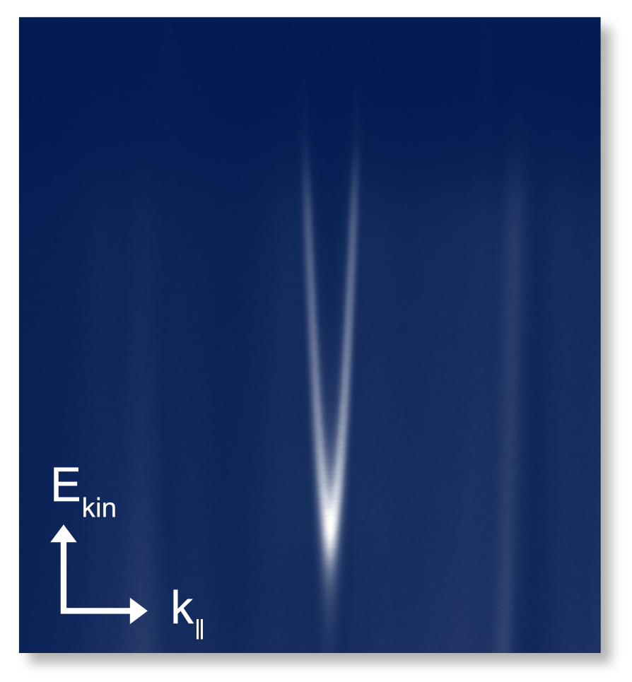
In contrast to the Double Dispersive Imaging Mode, the exit slit is fully open in this case. This energy dispersion image does not undergo the usual Fourier transformation behind the Imaging Energy Filter, but is directly projected onto the imaging unit (16). The measurement on the right shows the surface state of a Au (111) single crystal acquired by using the Energy Dispersion Mode of the NanoESCA · MARIS.
NanoESCA MARIS Specifications
| Property | Specification |
|---|---|
| Momentum Space Resolution | < 0.005 Å-1 |
| Momentum Space Field of View | 0.5 Å-1 .. 6.0 Å-1 |
| Momentum Space Operation Modes | Aberration Corrected Imaging, Double Dispersive Imaging, Energy Dispersion (E vs k) |
| Real Space Resolution | < 35 nm |
| Real Space Field of View | 6 μm .. 800 μm |
| Real Space Operation Modes | Aberration Corrected Imaging, Double Dispersive Imaging |
| Imaging Energy Resolution | < 25 meV |
| Energy Range (E – EF) | 0 eV .. 1595 eV |
| Contrast Aperture | Five discrete aperture sizes |
| Field Aperture | Continuously adjustable Iris aperture Discrete micro apertures available as option |
| Extraction Voltage | 50 V .. 20 kV |
| Electron Signal Amplifier | Double MCP |
| Imaging Unit Type | Fast S-CMOS camera |
| Imaging Unit Speed | Up to 140 frames/s |
| Electron Counting Mode | Analog or Event Counting |
| Imaging Spin Filter | Available as option |
| Time-of-Flight Energy Filter | Available as option |